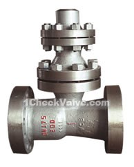
No-load Running Check Valve
manufacturer: Kaiweixi Valve Group Co., LTD.
E-mail: Yannie@kaiweixi.com
Tel: +86(577)67038872
Mob: +86 189 6779 6135(WeChat Same Account)
product drawing

No-load running check valves
Usages
175H48Y / H-type no-load running check valve is installed in the outlet pipelines of thermal power high-pressure large pump, to prevent water backflow, protect the pump. The valve matchs the pump minimum flow automatic recycling bypass valve for the work. When the pump is at low load or closed state in the outlet, the auto recycling bypass valve should be in the open position, to ensure the safe operation of water pumps. When the no-load running check valve is open, the auto recycling bypass valve will automatically close.
Structural features
1.As a principle: open the outlet valve, the pump starts, water reaches a certain pressure, and the disc will up to a certain hight under the water pressure, pushing away from the seat, water flows. At the same time, due to the rise of disc, drive ratating link rod, poke the drain piece, so that recycling blade valve moving down to close the evacuation part. When the water flow diminishs, the disc falls, promotes the link rod and poke the drain piece, open the recycling valve to maintain the minimum allowed flow of the water pump. When the pump stops, the disc automatically drop to close the valve channel, preventing the damage of high-pressure water hammer to the water supply system.
2.structural features:
a.the valve matchs with recycling bypass valve for the work, to maintain the safe operation of the system.
b.the main disc moves up and down, when the medium backflows, using medium pressure and the spring effect to close the pipes, and the bypass valve opens, when the main disc is full open, the bypass valve is closed.
c.The disc sealing adopts stainless steel bead welding, abrasion resistance, strong anti-scratch, reliable sealing.
d.the valve should be installed vertically.
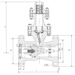
Dimensions & constructral diagram

No-load running check valve constructral diagram
The materials of main parts
| part name | materials |
| body,connecting flange,exhaust flange,flange cover | carbon cast steel |
| guided shaft, fork, shaft sleeve, slide,discharge bushing, exhaust plate | stainless steel |
| disc,disc body,disc shaft,connecting part | high quality carbon steel |
| sleeve | cast Aluminum Bronze |
| bolt, nut | high quality carbon steel |
Main performance and specifications
| nominal pressure PN(MPa) | test pressure Ps(MPa) | working pressure (MPa) | applicable medium | working temperature (℃) | |
| intensity test | sealing test | ||||
| 20.0 | 30.0 | 22.0 | 20.0 | water | ≤160 |
Main connection dimensions
| DN | L | D | D1 | D2 | D6 | b | Z-d | f | f2 | H | weight (kg) |
| 100 | 430 | 360 | 292 | 245 | 138 | 66 | 8-41 | 3 | 6 | 630 | 285 |
| 150 | 550 | 440 | 360 | 305 | 190 | 82 | 12-Ф48 | 3 | 6 | 650 | 510 |
| 175 | 610 | 475 | 3944 | 340 | 214 | 84 | 12-Ф48 | 3 | 6 | 685 | 700 |
| 225 | 900 | 580 | 483 | 418 | 268 | 100 | 12-Ф58 | 3 | 6 | 765 | 1105 |
| 250 | 900 | 670 | 572 | 508 | 319 | 110 | 16-Ф58 | 3 | 6 | 780 | 1330 |


