Hydraulic Lift Check Valve
manufacturer: Kaiweixi Valve Group Co., LTD.
E-mail: Yannie@kaiweixi.com
Tel: +86(577)67038872
Mob: +86 189 6779 6135(WeChat Same Account)
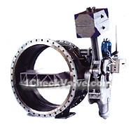
product drawing

Hydraulic lift check valves
Usages
The valve is suitable for water medium, installed in the pump outlet, used to avoid and reduce the the pipe system medium bakflowpump outlet pipe on the road, as a closed-circuit, and and the check valve is used to prevent and reduce overlarged water hammer caused by the piping system backflow, to protect the pipe systems. And it can replace two valves(the traditional pipeline design is gate valve matched check valve or normal butterfly valve matched with check valve).
Features
1.The control part adopts full hydraulic type, using accumulator replaced the heavy hammer part, reducing the energy loss, and the transmission is simplified, the occupy space is small, approximately to normal butterfly valve. The installation is convenient, can be installed horizontally left and right, or vertically.
2.The valve is installed after the pump, can replace gate valve (butterfly vale ) and check valve. And the flow resistance coefficient is small, oversized butterfly valve flow resistance coefficient is only slightly higher than gate valve. Therefore, this valve is energy-saving product.
3.When HD7Q41X valve closed, the fast and slow segments times and switch angles can be regulated according to the characteristics of pipeline system or customer requests, so as to achieve the elimination or decrease of water hammer, and protect the system.
4.If all travel switches adopt inductive proximity switches, to remove the hydraulic station, the protection class is up to IP67.
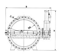
Dimensions & constructral diagram

Hydraulic lift check valve constructral diagram
Main technical parameter
| nominal diameter(mm) | 1400-2400 | 1200-2400 | 500-2400 | 500-2400 | 500-1600 | |
| nominal pressure(MPa) | 0.25 | 0.6 | 1.0 | 1.6 | 2.5 | |
| test pressure | intensity test | 0.375 | 0.9 | 1.5 | 2.4 | 3.75 |
| sealing test | 0.275 | 0.66 | 1.1 | 1.76 | 2.75 | |
| applicable medium | water | |||||
| suitable temperature(℃) | ≤80℃ | |||||
| medium flow speed | 3m/s | |||||
The materials of main parts
| part name | materials |
| body,disc | grey cast iron,ductile cast iron,carbon steel |
| shaft | SS |
| sealing ring | SS, NBR |
| packing | NBR |
Implement standard
| design standard | JB/TB527-97、GB/T 12238-89 |
| flange standard | GB/T 17241。6-1998、GB2555-2556-81 |
| face to face dimension | GB12221-89 |
| test standard | GB/T 13927-92 |
Main external and connection dimensions
| DN | PN | D | D1 | B | L | A | B | H |
| 500 | 1.0 | 670 | 620 | 43 | 229 | 720 | 1650 | 1360 |
| 600 | 1.0 | 780 | 725 | 48 | 267 | 720 | 1730 | 1390 |
| 700 | 1.0 | 895 | 840 | 54 | 392 | 720 | 1800 | 1445 |
| 800 | 1.0 | 1015 | 950 | 58 | 318 | 720 | 1870 | 1485 |
| 900 | 1.0 | 1115 | 1050 | 61 | 330 | 720 | 2070 | 1865 |
| 1000 | 1.0 | 1230 | 1160 | 67 | 410 | 755 | 2165 | 1930 |
| 1200 | 1.0 | 1455 | 1380 | 65 | 470 | 905 | 2265 | 2030 |
| 1400 | 1.0 | 1675 | 1590 | 68 | 530 | 905 | 2665 | 2270 |
| 1200 | 0.6 | 1405 | 1340 | 65 | 470 | 755 | 2365 | 2025 |
| 1400 | 0.6 | 1630 | 1560 | 68 | 530 | 755 | 2665 | 2270 |
| 1600 | 0.6/0.25 | 1830 | 1760 | 68 | 600 | 905 | 2940 | 2380 |
| 1800 | 0.6/0.25 | 2045 | 1970 | 70 | 670 | 905 | 3325 | 2470 |
| 2000 | 0.25 | 2265 | 2180 | 54 | 760 | 905 | 3660 | 2370 |
| 2200 | 0.25 | 2475 | 2390 | 60 | 840 | 1123 | 4325 | 2940 |
| 2400 | 0.25 | 2685 | 2600 | 62 | 910 | 1123 | 4530 | 3000 |


