High Pressure Heater Exit Check Valve
Dimensions & constructral diagram
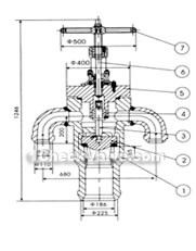
DN175 High pressure heater exit check valve constructral diagram(pic1)
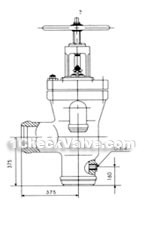
DN175 High pressure heater exit check valve constructral diagram(pic2)
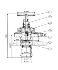
DN175 High pressure heater exit check valve constructral diagram(pic3)
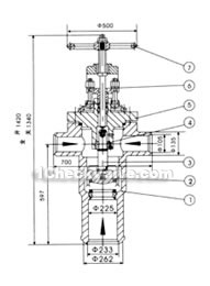
DN225 High pressure heater exit check valve constructral diagram(pic4)
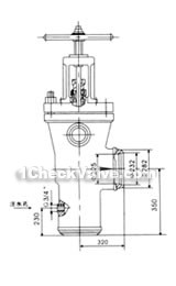
DN225 High pressure heater exit check valve constructral diagram(pic5)
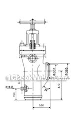
DN300 High pressure heater exit check valve constructral diagram(pic6)
Usages
DNl75 is installed in the 50MW generating units, DN225 is installed in the 100MW units, DN300 is installed in the 200MW units of high-pressure heater exit water supply pipes and match with the valve entrance. When the enter valve closed, the check valve is also closed, the supply water switch to the bypass, the high pressure heater disconnects safely.
Structural features
1.The valve should be installed vertically.
2.Seat sealing surface is welded by cobalt-based hard alloy plasma, with good wear resistance, good anti-abrasion, and good performance.
3.After corrosive resistance nitrogen treatment, the stem surface has good corrosive resistance and scratch resistance.
4.Using handwheel to make the stem rotate to the highest position when operation.
The materials of main parts
| No. | part name | materials |
| 1 | body | carbon steel |
| 2 | disc | carbon steel |
| 3 | stem | nitriding steel |
| 4 | sleeve | Aluminum bronze |
| 5 | bonnet | carbon steel |
| 6 | stem | ammonia permeability steel |
| 7 | handwheel | cast iron |


